I mentioned earlier, that I was designing a system for a company. The system was to be built with scrap and things you could find in everyday use. The Werner producer was perfect for this task since it is mostly made out of containers and gas bottles.
I first wanted to construct a prototype to make sure that it worked perfect and document the construction process. It took me three days to construct it and it worked really well. This design is made for a 2-litre engine.
More information and advice can be found at Werner’s website: www.gengas.se

Note that the following items are missing on this prototype:
Spring holding on the hatch
Condensate collector
Flap valve in the air intake
Flame killer
Hatch for taking out ash
Part list:
220 mm oxygen gas tube. Should be circa 7 mm thick gods.
300 mm tank (propane tank)
One fuel container (ca 500 mm diameter and 1000 – 1500 mm high)
3 mm sheet steel
8 mm concrete reinforcement steel
10 mm pipe
Heating-pan string
Nuts with 8 mm inner diameter
12 mm nut and bolt
Blower of some kind
So this is how you do it!
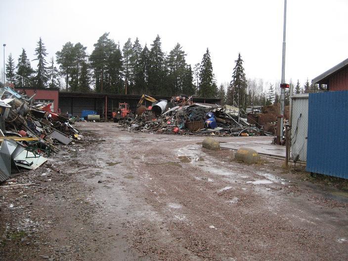
Go to the scrap yard and find all nice stuff you need!
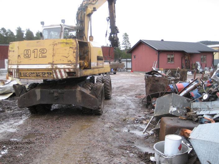
If the scrap yard owner is a nice guy, he’ll carry the heavy things to your car with his magneto-tractor.
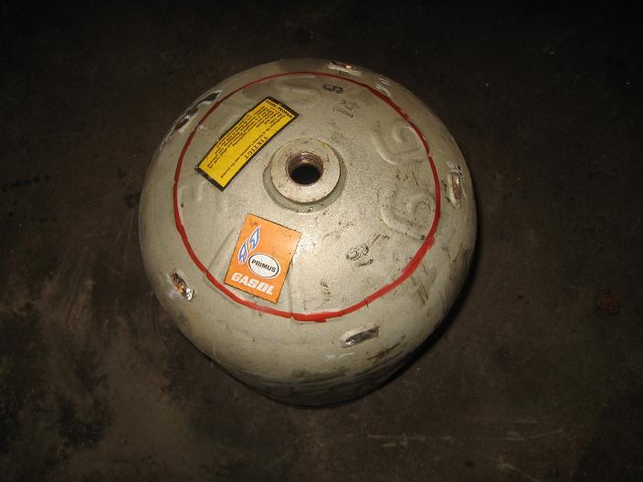
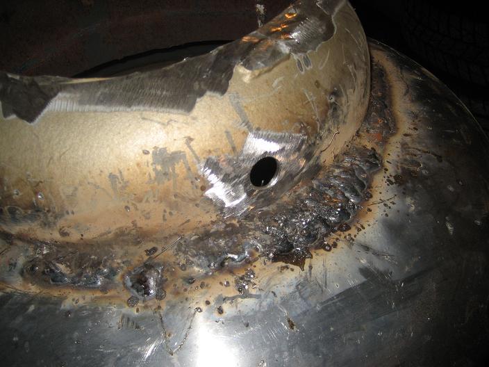
Now, let’s start working! Fill the 300 mm Propane tank with water and empty it to get rid of the gas. Mark the top with a diameter of 220 mm and cut it.

Cut the propane tank 100 mm from the new hole. Cut a 310 mm hole in one end of the fuel container and a 300 mm hole in the other end. Take care of the 310 mm end, because we’re going to need it later. (Fuel container is not in picture)
Weld the bit of the propane tank 30 mm into the fuel container (on the 310 m side). Use concrete steel to fill the space if needed. This will be the combustion zone. Drill five 15 mm holes symmetric round the bit (for the nozzle pipes).

Cut the nozzle pipes into 35 mm pieces. We use nuts with an inner diameter of 8 mm for nozzles. Weld them to the pipes.
Weld the pipes to the holes.
The nozzles can be fixed with a magnet while welding.
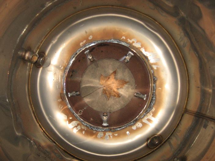
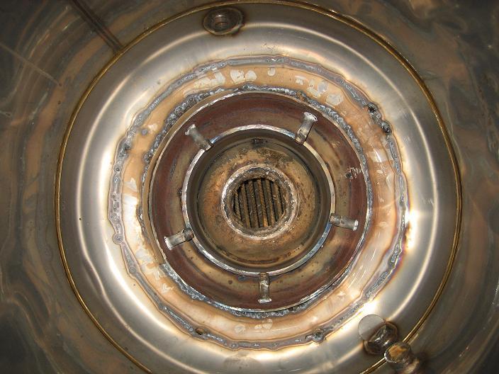
This is the inside view of the combustion zone.

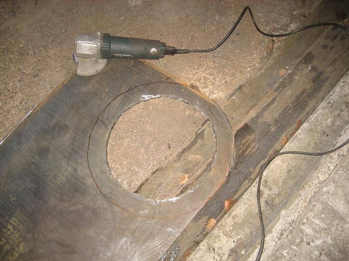
Cut the oxygen tube so there will be a 70 mm opening in the top. Then cut the tube 90 mm further down. This will become the reduction zone cone.

Hone the 70 mm hole in the cone from the inside to 80 mm. Take a nice piece of Swedish concrete steel.

Weld the concrete steel around the 80 mm hole.

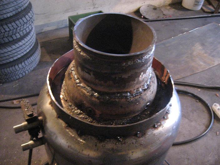
Cut a 130 mm piece of the oxygen tube and weld it on top of the cone.
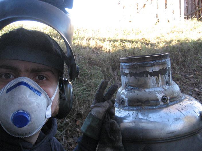
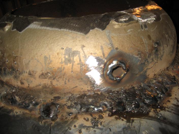
Weld the tube with the cone 20 mm into the combustion zone and look smart in front of the camera.
Cut a 50 mm strip of sheet steel and make a ring round the air nozzle intakes.
Cut a plate to seal the area inside the ring.
Weld it!

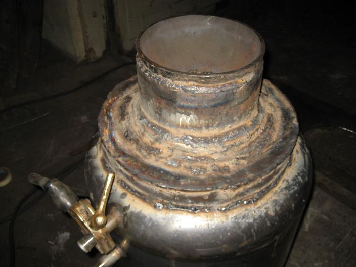
Cut a 15 mm ring of the propane tank. Weld it on the top of the fuel container.
Cut stripes of sheet steel and weld them to the 310 mm piece that we cut of the fuel container.
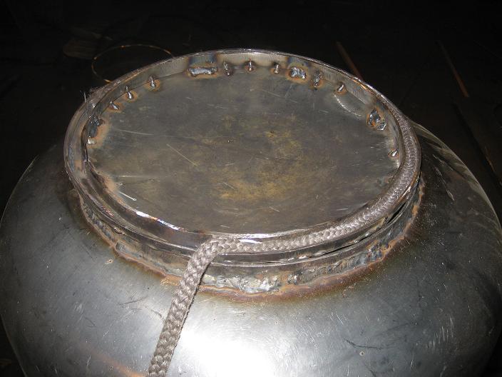
Add warming-pan string and we got our selves a hatch for the producer!
Tada!
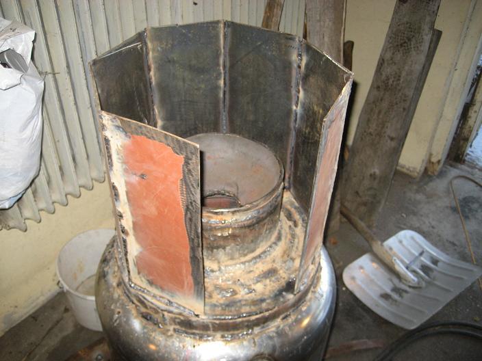
Start coating in the reduction zone with 350 mm long pieces of sheet metal. A 400 mm x 350 mm long canister could also be used.
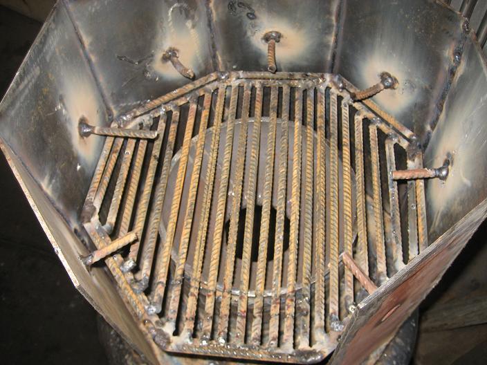
Make a grid of 8 mm concrete steel. The spaces between should be 4 mm (the picture shows 6 mm). The grid should have 10 mm of space on each side to be able to move. Weld something to the wall that will hold the grid 50 mm beneath the cone. If possible – make it cover the space so that coal won’t fall down.
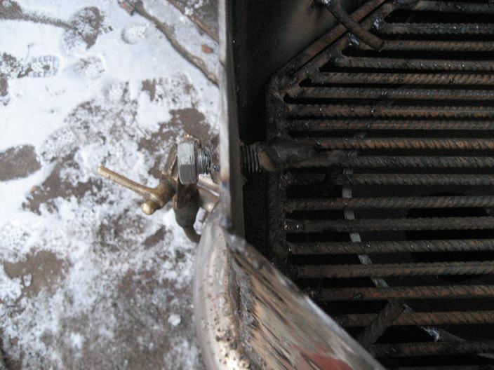
Make a hole and weld a nut on the wall just beneath the grid. Screw a bolt into the nut and weld concrete steel to it, so it moves the grid while turning.
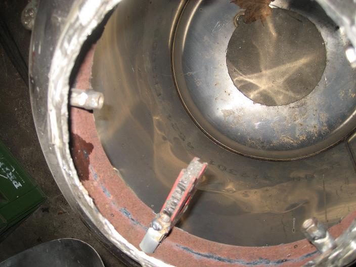
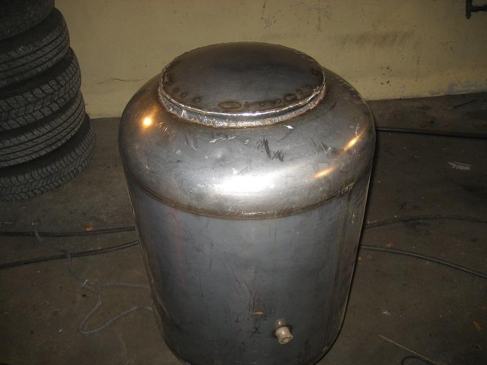
This is how the producer should look like from the inside.
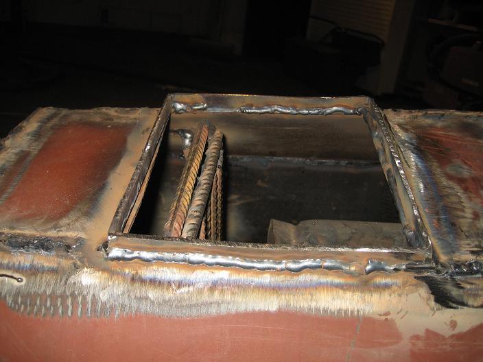
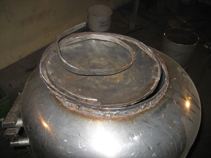
Use sheet metal stripes to create a flange around the opening to the reduction zone.
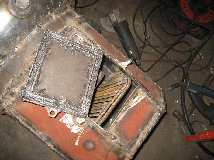
Make a hatch.
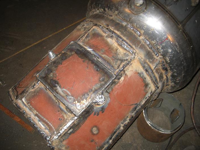
Put it on the opening and give it a jolly good knock!
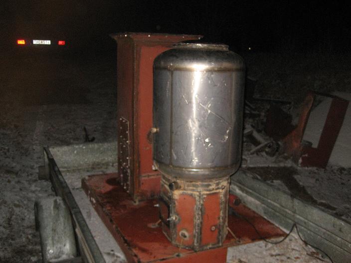
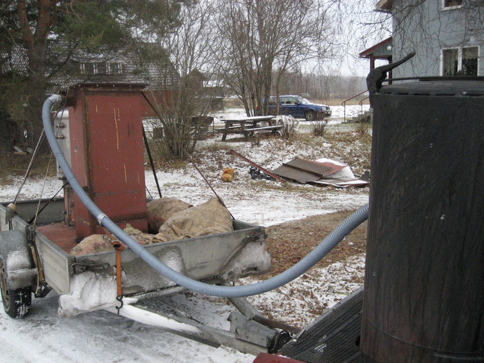
Now, if you are anxious to get things going like me – you don’t care about that it’s night and your neighbours wanting to strangle you. So mount the producer and an old filter on a trailer.
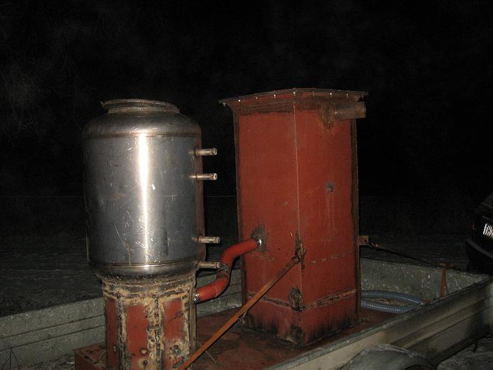
Connect the units with some pipe.
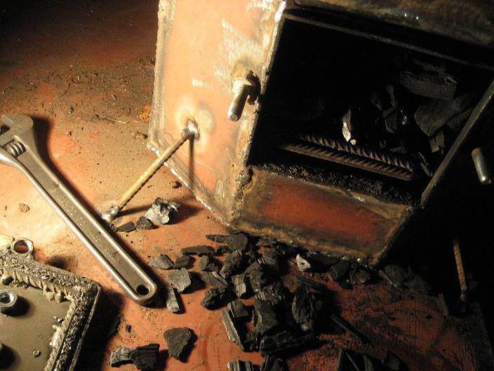
Load with charcoal and wood.
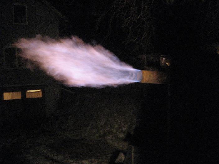
Connect a blower and light the producer. There is nothing like the lovely blue colour of home made CO!

The flame shows no signs of tar in the gas.
The car started quickly with the new producer and ran really well. I connected the prototype system to the car with a hosing.
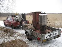
/Johan